Showing posts with label Graphics. Show all posts

Saturday, March 7, 2015

Derivative Mapping

I've been somewhat unhappy with the lighting on my terrain for a while now especially the way much of the time it looks pretty flat and uninteresting.  It's using a simple directional light for the sun at the moment along with a secondary perpendicular fill light as a gross simulation of sky illumination plus a little bit of ambient to eliminate the pure blacks.  Normals are generated and stored on the terrain vertices but even where the landscape is pretty lumpy they vary too slowly to provide high frequency light and shade and with no shadowing solution currently implemented there's not much visual relief evident leading to the unsatisfying flatness of the shading.

While I plan to add shadowing eventually I don't want to open that can of worms quite yet so I had a look around for a simpler technique that would add visual interest.  I thought about adding normal mapping but the extra storage required for storing tangent and binormal information on the vertices put me off as my vertices are already fatter than I would like.  While looking in to this however I came across a blog post by Rory Driscoll from 2012 discussing Derivative Mapping, itself a follow up to Morten Mikkelsen's original work on GPU bump mappng.  This technique offers a similar effect to normal mapping but uses screen space derivatives as a basis for perturbing the surface normal using either the screen space derivatives calculated from a single channel height map texture or the pre-computed texture space derivatives of said height map stored as a two channel texture.

This was appealing to me not just because I hadn't used the technique before and was therefore interested just to try it out, but also from an implementation point of view I would not have to pre-compute or store anything on the vertices to define the tangent space required for normal mapping saving a considerable amount of memory given the density of my geometry.  It also solves the problem of defining said tangent space consistently across the surface of a sphere, a non-trivial task in itself.

Thanks to the quality of the posts mentioned above it was a relatively quick and easy task to drop this in to my terrain shader. I started with the heightfield based version as with the tools I had available creating a heightfield was easier than a derivative map but while it worked the blocky artifacts caused by the constant height derivatives where the heightmap texels were oversampled were very visible especially as the viewpoint moved closer to the ground.  I could have increased the frequency of mapping to reduce this but when working at planetary scales at some point they are always going to reappear.  To get round this I moved on to the second technique described where the height map derivatives are pre-calculated in texture space and given to the pixel shader as a two channel texture rather than a single channel heightmap.  The principle here is that interpolating the derivatives directly produces a higher quality result than interpolating heights then computing the derivative afterwards.  I had to write a little code to generate this derivative map as I didn't have a tool to hand that could do it but it's pretty straightforward.

Although this takes twice the storage and a little more work in the shader the results were far superior in my context with the blocky artifacts effectively removed and the effect under magnification far better.


A desert scene as it was before I started.  With the sun overhead there is very little relief visible on the surface
The same view with derivative mapping added.  The surface close to the viewpoint looks considerably more interesting and the higher frequency surface normal allows steeper slope textures to blend in
As you can see here the difference between the two versions is marked with the derivative mapped normals showing far more variation as you would expect.  The maps I am using look like this:


The tiling bump map I am using as my source heightfield
The derivative map produced from the heightfield.  The X derivatives are stored in the red channel and the Y in the green.


Here is another example this time in a lowlands region:


A lowlands scene before derivative mapping is applied
The same scene with derivative mapping.
Particularly evident here is the additional benefit of higher frequency normals where it is the derivative-mapped normal not the geometric one that is being used to decide between the level ground texture (grass, sand, snow etc.) and the steep slope texture (grey/brown rock) on a per-pixel basis.  This produces the more varied surface texturing visible in the derivative mapped version of the scene above.

Finally, here are a couple more examples, one a mountainous region the other a slightly more elevated perspective on a mixed terrain:


Mountain scene before derivative mapping
The same scene with the mapping applied, the mountain in the foreground shows a particularly visible effect 
A mixed terrain scene without mapping
The same scene with the derivative mapping applied.  The boundaries between the flat and steeply sloped surface textures in particular benefit here with the transitions being far smoother
To make it work around the planet a tri-planar mapping is used with the normal for each plane being computed then blended together exactly as for the diffuse texture.  For a relatively painless effect to implement I am very pleased with the result, the ease of use however is entirely down to the quality of the blog posts I referenced so definitely thanks go to Rory and Morten for that.

Monday, March 2, 2015

In Deep Water

I've been thinking about water, particularly how the oceans of a planet affect the evolution of the people living on it, their choices for habitation, agriculture and infrastructure.  Of course there are many other factors that influence these things but oceans seem like a good place to start, and with 71% of the Earth covered by them there is certainly plenty of reference material about.

I had a couple of thoughts about how to procedurally generate the water masses for my planet, the most straightforward and probably most commonly used is to simply decide upon an elevation level to define as the sea level with everything generated by the noise functions under that counting as water.  You can then render the water at that elevation and the GPU's Z buffer will sort out the intersection with the land.  While I still want the simplicity and benefits of an established sea level, I wanted to have a look at making water region generation more integral to the overall planet's procedural system rather than it being treated essentially as a post process.  

Eventually it would be nice to have bodies of water at different elevations so mountain lakes, tarns and similar could be created preferably with rivers and streams connecting them to each other, waterfalls and larger bodies of water but that's all for the future.

The TL;DR version: this video shows the effect I'm going to describe here as it now stands:


To make water body creation part of the terrain system the heightfield generation itself has to be aware of the presence of water so there needs to be a way to define where the water should go.  My first attempt at this was using the country control net as I thought the country shapes would make pretty decent seas and by combining a couple of adjacent ones some reasonable oceans.  By creating the countries as normal then simply flagging some of them as water such regions can be established, the heightfield generator can then ray-cast the point under consideration against the country net and if it finds it's within a water "country" use a noise function appropriate for sea beds that will return low altitude points below the global sea level.

When I tried this however a couple of points became apparent, firstly having to ray cast against the country net's triangulation slows down the heightfield generator which is significant when it has to be run so frequently to generate the terrain and while optimisation might mitigate some of this cost I felt a more significant problem was the regularity of the water zones created.  With each being formed from a single country there were for example no islands generated which is quite a big drawback and for me pretty much discounted this approach.

Instead of the country net then how about using the terrain net instead?  By adding a terrain type of Ocean that generates a plausible seabed heightfield that lies below sea level to the existing terrain types such as mountain, hilly and desert deep water regions could be formed using the same controllable system employed for those other type of terrain.  The turbulence function described previously that perturbs the terrain type determination will also then affect the water region borders creating some interesting swirls and inlets.

The blending of mountainous or hilly terrain into the seabed generator around the transition areas also produces plenty of islands of various sizes


Islands formed by perturbing the ray cast against the terrain net
There are some drawbacks to using the terrain net instead of the country one however, there is nothing for example to prevent an entire country from ending up under water or possibly more problematically the vast majority of a country could be under water leaving an implausibly small section remaining that simply would not really exist in the real world.  On balance however I thought this is the better of the two systems so am going with this for now.


Rendering Water

Rendering of realistic water is a long standing challenge for real time graphics and one that I've looked at myself from time to time in my various forays into terrain generation and rendering. For this project I thought a good place to start with generating the actual geometry for the water surface would be to use essentially the same system as I already use for the terrain, namely a subdivided icosahedron.

The existing triangular patch generator can easily be extended to determine whether any vertices in the patch are below sea level or not, and if so a second set of vertices for the ocean level surface patch is generated.  These vertices represent the triangular area of the surface of a sea level radius sphere centred on the centre of the planet and encompassed by the patch in question. Although the plan is to have realistic waves on the water these will be generated by the vertex shader displacing the vertices so a smooth sphere is enough to start with.


Wireframe of the water surface before being perturbed in the vertex shader using the displacement of the simulated water surface
The level of detail system described previously can also be leveraged to decide which water geometry patches to render by simply running it in parallel on both the terrain patches and the water ones - a different distance scalar can also be used for the water patches enabling lower detail geometry to be used for the water potentially improving performance as long as the visual quality doesn't suffer too much.

Even though the identical geometric topology allows the water patches to use the same index buffer as the terrain there is an additional and more significant optimisation opportunity here that would save significant memory.  With each water patch representing what is essentially an identical shaped section of the sphere's surface at that level of detail they could actually all be drawn using a single vertex buffer with a suitable transformation matrix to put it at the correct position and with the correct orientation.  Setting this up is a little fiddly so I'm leaving it for a future task but should memory become an issue it's likely to be one of the first things I'll revisit.

As for the actual water visuals, the movement and appearance of water is notoriously difficult to simulate especially as the real thing behaves so radically differently in different situations - shallow water is totally different to deep for example and white water rapids completely at odds with languid meandering rivers.  To make such a difficult problem manageable I chose to focus on just one aspect and when talking at planetary scales deep water seemed like the logical choice - the oceans created as described above will dominate any other water features I add in the future.

There are quite a few references and demos for deep water rendering but the one I chose was the NVIDIA "Ocean" demo from their now superceded graphics SDK which is in turn based on such classic work as Jerry Tenssendorf’s paper “Simulating Ocean Water”. I liked this demo as it is well documented and being GPU based heavily targeted at real time graphics.

This demo uses a couple of compute shaders to perform the necessary FFT followed by a couple of pixel shaders to produce two 2D texture maps, one storing the displacement for the vertices over the square patch of water and the other storing the 2D gradients from which surface normals can be calculated and a 'folding' value useful for identifying the wave crests.


High LOD wireframe showing how the smooth sphere vertices have been displaced to create the waves.  Note that normally a lower LOD version is used as the majority of the shading effect comes from the normals computed in the pixel shader rather than the wave shapes produced in the geometry.
The displacement map is fed in to the water geometry's vertex shader to displace the vertices creating the waves while the gradient/folding texture is fed in to the pixel shader to allow per-pixel normals to be created for shading and wave crest effects to be added.

Using these textures as the primary inputs, there are a number of shading effects taking place in the pixel shader here to give this final ocean effect.  Although the NVIDIA demo produces a nice output I decided to largely ignore the final pixel shader as it's use of a pre-generated cube map for the sky colour along with a simulated sun stripe was a bit too hard coded for my needs.  Instead I fiddled around some and came up with my own shading system.

Firstly the gradient texture is used to compute a surface normal which is then used with the view vector to calculate the reflection vector (using the HLSL reflect function).  I then create a ray from the surface point along that reflection vector and run it through the same atmospheric scattering code that is used for rendering the skybox, this gives me the colour of the sky reflected from that point and ensures that the prevailing sky conditions at that location at that time of day are represented.  This is important to ensure effects such as sunsets for example are represented in the water but even at less dramatic times of the day gives the water somer nice variegated shades of blue.


Bright early morning sun reflected in the water
The last traces of sunset bounce off the ocean surface, an effect that would be difficult to achieve with direct illumination
Capturing the sun's contribution in this unified manner is especially useful as it's size and colour varies so much based upon the time of day, trying to represent that as a purely specular term on water can be a challenge often ending up with a sun "stripe" that doesn't match the rendered sun - especially near the horizon.

The folding value from the gradient texture is used to add a foam effect at the top of the waves to make the water look a bit choppier.  The foam texture itself is a single channel grayscale image with the degree of folding controlling which proportion of the grayscale is used.  A low folding value for example would cause just the brightest shades of the foam texture to be used while a high one would cause most or all of the greyscale to be present producing a much stronger foam component to the final effect.  A global "choppyness" value is also used to drive the water simulation which affects how perturbed the surface normals are in addition to introducing more foam - this value can be changed dynamically to vary the ocean from a millpond to a roiling foamy mass: 


A fairly low "Choppyness" value produces pleasing wave crests and moderate surface peturbation
A higher "Choppyness" produces more agitated wave movement, sharper surface relief and considerably more foam.
In addition to foam at the wave crests I also wanted foam in evidence where the water meets the land, to accomplish this a copy of the depth buffer is bound as a pixel shader input and the depth of the pixel being rendered compared against it.  This produces a depth value representing the distance between the water surface and the terrain already rendered to that pixel.  This depth delta is added not just to the foam amount to render but is also used to drive the alpha component letting the water fade out in the shallows where it meets the land.  This can be seen in both the images above where the water meets the land.

The benefit of using the screen space depth delta rather than a pre-computed depth value stored on the vertices is that it reacts dynamically to both the movement of the vertices driven by the water surface displacement map and to anything else that penetrates the water surface.  The latter can't be seen just yet other than where the water geometry meets the terrain as I don't have any such features but in the future should I have ships, jetties or gas/oil rigs the alpha/foam effect will simply work around where they intersect the water helping them feel more grounded in-situ.


Problems of scale

As mentioned above one of the fundamental problems with water rendering is that it behaves and appears so radically different depending on it's situation, but another problem with rendering water especially with planetary scale viewpoints is how it appears from different distances. The 512x512 surface simulation grid I'm using looks good close up but simply tiling it produces unsightly repeating patterns when viewed from larger distances.


Not only does the limited simulation area become very apparent but the higher frequency of the surface normal variation produces very visible aliasing in both the reflection vector used to compute the water colour and the wave crest effect producing unsightly sparkling in the rendered image.

Rather than simply increase the simulation area which would produce just a limited improvement and incur increased simulation cost instead I vary the frequency at which I sample the simulated surface with distance.  The pixel shader uses the HLSL partial derivative instructions to determine an approximate simulation texture to screen pixel ratio then scales the texture co-ordinates to obtain an equally approximate 1:1 mapping.  This effectively causes the simulation surface to cover increasingly large areas of the globe as the viewpoint moves further away.

This is in no way physically accurate but produces a more pleasing visual effect than the aliasing, and by blending between adjacent scales a smooth transition can be achieved to hide what would otherwise be a very visible transition line between scales - an effect very similar to a mip line when trilinear or anisotropic filtering is not being used.  Take a look at the second half of the video above to see how this looks in practice as the viewpoint moves from near the surface all the way out into space.

There is more to the effect than just scaling the simulated water surface to cover larger and larger areas though, as while this eliminates most of the tiling artifacts it also inevitably makes all water features larger which can look increasingly unrealistic. To alleviate this undesirable consequence certain aspects of the effect are toned down with increasing distance from the viewpoint.  The first is the per-pixel normal calculated from the simulation's gradient texture which has the gradient's effect scaled down to produce less variation with distance making the resultant variations in reflected sky colour more subtle while the second is the foam wave crest effect which is also scaled down and ultimately removed with distance:


More distant view showing how the wave crests peter out and the water adopts a smoother aspect with distance

Combining these helps make distant water a bit more appropriately indistinct.  


Making it all 3D

The final challenge with the water was taking the two dimensional result of the simulated water surface and applying it to my three dimensional planet.  There are a variety of ways to map 2D squares to the surface of a sphere but each has major trade-offs involving distortion in some way or other.  I decided to keep it simple and use the same triplanar projection system used for texturing the terrain - i.e. using the 3D world space position of the point being shaded to sample the texture in the XZ, XY and ZY planes then using the surface normal to blend between them.

The only trick here is to make sure the directions of the normals from the gradient map are consistent so they are oriented correctly for the plane they are being applied to, getting this wrong and the sun and sky will not reflect properly in the water.


Next Steps

I'm pretty happy with the water effect now, it has some artifacts still but I feel I've spent enough time on it for now and the effect is good enough not to irritate me.  Next I think is integrating it's placement more into the geographic terrain generator especially in the area of trying to make interesting coastlines along with processing it's impact on the countries themselves.

Saturday, January 17, 2015

Terrain Visuals

My posts on this particular project so far have been about preparation for generating a plausible political landscape complete with infrastructure rather than the physical landscape most of my other projects have focussed on but before I go any further I think it necessary to have at least enough of a physical landscape to make placement and routing of the more man made features interesting..putting things on a flat coloured sphere is only going to hold my attention for so long I expect!

While I've previously worked with voxels to facilitate truly three dimensional terrain including caves and the like with the focus of this project elsewhere the simplicity of a heightfield based terrain makes sense.  When doing this in the past I've used a distorted subdivided cube as the basis of the planet - taking each point and normalising it's distance from the planet centre to produce a sphere - which has some benefits for ease of navigation around each "face" and for producing a natural mapping for 2D co-ordinates but the stretching produced towards where the cube faces meet is unpleasant and besides, I've done that before.

Caveat: Before I go any further however I should point out that nothing I am doing here is rocket science - if you have ever done your own terrain projects in the past the odds are nothing here is news to you but I'm presenting what I'm doing as it will hopefully form the basis for more interesting things to come or if you're thinking about a terrain project for the first time perhaps it will be of use.


The Base Polyhedron

For this project therefore I've chosen to base my planet on a regular Icosahedron, a 20 sided polyhedron where each face is an equilateral triangle.  The geometry produced by subdividing this shape is more regular than the distorted cube as you are essentially working with equilateral triangles at all times.  Each progressive level of detail takes one triangle from the previous level (or one of the 20 base triangles from the Icosahedron at the first level) and turns it into four by adding new vertices at the midpoints of each edge.  Each of the new vertices is then scaled to put it back on the unit sphere:


Subdividing an equilateral triangle into four for the next level of detail produces three new vertices and four triangles to replace the original one.
This is about as simple a scheme as you can get and can be found in many terrain projects, but simplicity is what I'm after here so it's perfectly suited.  As modern graphics hardware likes to be given large numbers of triangles with each draw call rather than render single terrain triangles the basic unit I render (which I'm calling A Patch) is a triangle that's already been subdivided eight times, producing an equilateral triangle shaped chunk of geometry that has 256 triangles along each edge - a total of 65,536 triangles which should feed the GPU nicely especially as they are drawn as a single tri-strip.  Were I to draw the entire planet at my lowest level of detail then I would be drawing 20 of these patches giving around 1.3 million triangles which empirical testing has shown my GPU eats up without pausing for breath.  Good start.


Level of Detail (LOD)

While a million triangles might not give a decent GPU pause for thought these days, what this does show is that with each level of subdivision multiplying the triangle count by four you do get to some pretty high triangle counts after just a few levels of subdivision.  With planets being pretty big as well, those million triangles still don't give a terribly high fidelity rendition of the physical terrain - on an Earth sized planet the vertices are still more than 26 Km apart at this level,

As the viewpoint moves towards the planet's surface then I need to subdivide further and further to get down to a usable level of detail, but by then the triangle count would probably be too much to even store in memory never mind render were I to try to render the entire planet at that detail so of course some sort of level of detail scheme is required.

In keeping with my general approach the scheme I'm using is simple, when rendering I start by adding the 20 base patches mentioned above to a working set of candidates for rendering, then while that set isn't empty I take patches out of it and first test them for visibility against the view frustum then again against the planet's horizon in case they are effectively on the back side of the planet.  If either of those tests fail I can throw the patch away, but if both pass I then calculate how far away from the viewpoint it's centroid is and if less than a certain factor of the patch's radius I subdivide it into four patches at the next level of detail and add those into the set of patches for further consideration.  If the patch is not near enough to the viewpoint to be subdivided I add it to the set of patches to render.

The end result is a set of patches where near to the viewpoint are increasingly subdivided patches - i.e higher LOD each covering a smaller area at a higher fidelity - while moving away from the viewpoint are progressively lower LOD level patches each covering larger areas of the terrain at lower fidelity.  The ultimate goal is to provide a roughly uniform triangle size on screen across all rendered patches, note that this is intentionally a pretty basic system with no support for more advanced features such as geomorphing so the LODs pop when they transition but it's good enough for my purposes.


Colour-coded patches of different LODs, note how the triangle size is different in each colour with the smaller triangles closest to the viewpoint
A useful feature of the system is that by changing the threshold factor used to decide whether to subdivide a patch or not a simple quality control can be established.  Increase the threshold and patches will subdivide at greater distances increasing the number of patches and therefore triangles rendered using higher detail representations increasing fidelity but lowering performance while decreasing the threshold has the opposite effect - patches subdivide closer to the viewpoint causing fewer high detail patches to be rendered reducing the triangle count and improving performance at the expense of graphical fidelity


At low detail (a large transition distance) the geometry is relatively coarse.  900K triangles are being rendered here
Moving the transition distance towards the viewpoint gives a medium detail level with more higher detail patches being rendered making the triangles near the viewpoint smaller to improve fidelity.  1.8 Million triangles are being rendered here
Closer still and we have a high detail level with even more high detail patches being used.  5.7 Million triangles are being rendered here with the ones near the viewpoint almost a pixel in size.
In theory this value could be changed on the fly as the frame rate varies due to rendering load to try to maintain an acceptable frame rate, but I just set it to a decent fixed value for my particular PC/GPU for now.

As anyone who has worked with terrain LODs before will tell you however this is only part of the solution, where patches of different LODs meet you can get cracks in the final image due to there being more vertices along the edge of the higher LOD geometry than along the edge of the lower LOD geometry.  If one of these vertices is at a significantly different position to the equivalent interpolated position on the edge of the lower LOD geometry there will be a gap.  Note that as the higher LOD geometry is typically closer to the viewpoint you only tend to see these in practice where the vertex is lower than the interpolated position otherwise the crack is facing away from the viewpoint and is hidden.
Cracks between patches of different LODs due to the additional vertices on the high detail patch not lining up with the edge they subdivide on the lower detail patch.  (Note I've zoomed in on the effect here to highlight it, whilst still visible normally the cracks are much smaller on screen)
There are various ways to tackle this problem, one I've used before is to have different geometry or vertex positions along the edges of higher LOD patches where they meet lower LOD patches so the geometry lines up, but this adds complexity to the patch generation and rendering, and in it's simplest form at least limits the LODing system to only support changing one level of LOD between adjacent patches.

For this project I've taken a different approach and rather than changing the connecting geometry I generate and render narrow skirts around the edges of each patch.  These are the width of one triangle step, travel down towards the centre of the planet and are normally invisible but where a crack would exist their presence fills that gap hiding it with pixels that while not strictly correct are good enough approximations to be invisible to the eye.  The pixels aren't correct as they are textured with the colours from the skirt's connecting edge on the patch so are a stretchy smear of vertical colour bars but like I say they are close enough, especially as the gaps are usually just a pixel or two in size when using reasonably dense geometry.
With one triangle wide skirts on the patches the gaps are filled with pixels close enough to the surface of the patches in colour that they become invisible to the eye.
Comparing the before and after in wireframe makes the strip of new geometry along the join clear:


Wireframe without the skirts shows why the cracks appear
Wireframe when rendering the patch skirts shows the additional strip of geometry pointing straight down from the edge of the lower detail patch.  The higher detail patch also has a skirt but here they are back facing and culled by the GPU.
This does of course add extra geometry to each patch (1536 triangles in my case with 256 tris along each patch edge) which I am always rendering regardless of the LOD transition situation to enable them to be sent with the same single draw call per patch, but this is a small GPU overhead and doesn't appear to have any practical effect on performance.


Floating Point Precision

Anyone who's had a go at rendering planets will almost certainly have encountered the hidden evil of floating point precision.  Our GPUs work primarily in single precision floating point which is fine for most purposes but when we're talking about representing something tens of thousands of kilometres across down to a resolution of a centimetre or two the six or so significant digits offered is simply not enough.  This typically shows up as wriggly vertices or texture co-ordinates as the viewpoint moves closer to the surface, certainly not desirable.

To avoid this I store the single precision vertices for each patch not relative to the centre of the planet but relative to the centre of the patch itself.  The position of this per-patch centre point is stored in double precision for accuracy which is then used in conjunction with the double precision viewpoint position and other parameters to produce a single precision world-view-projection matrix with the viewpoint at the origin.

That final point is significant, by putting the viewpoint at the world origin for rendering I ensure the maximum precision is available in the all important region closest to the viewer.


The Heightfield

So now I have a reasonable way to render my planet's terrain geometry viewed anywhere from orbital distances down to just a metre or so from the ground I need to generate a heightfield representative enough of real world terrain to make placement of settlements and their infrastructure plausible.  I've played around with stitching together real world DEM data before but have never been too happy with the results, especially when trying to blend chunks together or hide their seams, so for this project I'm sticking to a purely noise based solution for the basic heightfield.

Relying so heavily on noise made me wary however or re-using my trusty home grown noise functions so instead I've opted to use the excellent LibNoise library which produces quality results, is very flexible, is fast and importantly for this multi-core world is thread safe - the last being particularly important  
as I have a huge number of samples to generate.

A common feature of purely noise based heightfields however that you see frequently on terrain projects is that they tend to look very homogeneous with very similar hills and valleys everywhere you look.  To make my planet more interesting I wanted to try to get away from this so had a think about how to introduce more variety.

The solution I came up with was to implement a suite of distinct heightfield generators each using a combination of noise modules to produce a certain type of terrain.  As a starting point I went with mountainous, hilly, lowlands, mesas and desert, but how to decide which terrain type to use where?  One solution would be to use yet another noise function to drive the selection, but I thought it would be interesting to try something else, and ideally a solution that gave me more control over the placement of different terrains while still providing variety.  The control aspect would allow me to make general provisions for placement such as having deserts more around the equator or mountains around the poles which feels useful. This doesn't violate my basic tenet of procedural generation - procedural isn't the same as random remember.


An example of the "Mountainous" terrain type, generated by a ridged multi-fractal
The "Hilly" terrain type uses the absolute value of a couple of octaves of perlin noise to try to simulate dense but lower level hills
The "Mesas" terrain type again uses octaves of noise but thresholds the result to produce low lying flatlands punctuated by steep flat topped hills
Instead of noise then I chose to use a control net similar to the country one detailed in my previous post, but instead of country IDs this time I put a terrain type on each control point - I also use the direct triangulation of the control net rather than the dual.  Shooting a ray from the planet's surface against this terrain control net gives me three terrain types from the vertices of the intersected triangle while taking the barycentric co-ordinates of the intersection point gives blending weight for combining them.


The terrain type control net.  Each vertex has a terrain type assigned to it so any point on the surface can be represented as a weighted combination of up to three terrain types.
Taking the result of each of these terrain type's heightfield generators, scaling by their blending weights then adding them together gives the final heightfield value.  There is an obvious optimisation here too where a triangle has the same terrain type at two or more of it's vertices - the heightfield generator for that terrain type can be run just once and the blending weights simply added together.


Here the "Hilly" terrain generator's result in the foreground is blending into the "Mountainous" terrain generator's result in the middle distance
I quite liked the idea of being able to craft each type of terrain separately so the look of the lowlands can for example be tweaked without affecting the mountains which can sometimes be tricky with monolithic noise systems, the frequency of terrain changes and their locations can also be controlled by changing the density of the terrain control net or playing with the assignment of terrain types to the control points.  For now I'm just assigning types randomly to each point but you could for example use the latitude and longitude of the point as an input to the choice or assign initial points then do some copying between adjacent points to produce more homogeneous areas where desired.


Texturing

An interesting heightfield is all well and good and whiled I've stated that physical terrain is not really the focus of this project I do want it to look good enough to be visually pleasing.  To this end I did want to spend at least some time on the texturing for the terrain so my desert could look different to my lowlands and my mesas different to my alpine mountains.  Past experience has shown me that one of the more problematic areas with texturing is where the different types of terrain meet, producing realistic transitions without an exorbitantly expensive pixel shader can be tricky.  The texturing also needs to work on all aspects of the geometry regardless of which side of the planet it's on or how steep the slope.

The latter problem is solved by using a triplanar texture blend, using the world space co-ordinates of the point to sample the texture once each in the XY, ZY and XZ planes and blending the results together using the normal.  This avoids the stretching often seen in textures on heightfields especially when not mapped on to spheres when a single planar projection is used but does of course take three times as many texture sample operations.  If you look closely you can also see the blend on geometry furthest from aligning with the orthogonal planes but as terrain textures tend to be quite noisy this isn't generally a problem - and is certainly less objectionable than the single plane stretching.

Using a single planar mapping in the XY plane produces noticeable texture stretching on the slopes

Changing to the XZ plane fixes most of those but produces worse stretching in other places
Third choice is the ZY plane but again we're really just moving the stretching artifacts around
The solution is to perform all three single plane mappings and use the world space normal to perform a weighted combination of all three.  Although this requires three times as many texture reads the stretching artifacts are all but gone.
As for which texture to use at each point I've adopted something of a brute force approach.  By keeping the palette of terrain textures relatively limited I am able to store a weight for each one on each vertex, in my case eight textures so the weights can be stored as two 32bit values on each vertex.  The textures I've chosen are designed to give me a decent spread of terrain types, so they include for example two types of grassland, snow, desert sand and rocky dirt.

Example basic textures for dirt, desert/beach sand and grass
By storing a weight for each texture independently I avoid any interpolation problems where textures meet as every texture is essentially present everywhere.  It does of course mean that the pixel shader in theory will need to perform up to eight triplanar texture mappings each requiring three texture reads (twice that if normal mapping is supported) but in practice most pixels are affected by only a couple of textures.  If I was doing this in a more serious production environment I would be thinking about having several variations of the pixel shader each specialised for a certain number and combination of textures to avoid potentially expensive conditionals or redundant texture reads but as this is just a play project one general purpose shader will suffice.


Blending the terrain type textures based purely upon the terrain control net.  The blending works but the linear interpolation artifacts along the net's triangulation boundaries are obvious and unsightly
While the textures blend together here the shape of the terrain control net is still quite obvious.  To improve matters I fell back to a technique I first trialled while playing with the country generation code, by perturbing the direction of the ray fired from the surface against the terrain control net more variety can be included while still offering the controllability of the net.

Applying a few octaves of turbulence to the ray gives a much more organic effect:
Using some turbulence to perturb the ray from the planet's surface before intersecting it with the terrain control net produces a far more satisfyingly organic and pleasing effect
I'm particularly happy with how this looks from orbital distances but it will suffice closer to the surface for now as well.


A Note on Atmospheric Scattering

You may have noticed in these screenshots that I've also added some atmospheric scattering.  For terrain rendering this is one of the most effective ways of both improving the visuals and adding a sense of scale - taking it away makes everything look pretty flat and uninteresting by comparison:


Without the atmospheric scattering the perspective and scale is unclear
With atmospheric scattering the sense of scale and distance is much improved
In a previous project I implemented the system published in Precomputed Atmospheric Scattering by Eric Bruneton and Fabrice Neyret which produced excellent results, but in the spirit of trying new things I thought for this project I would try Accurate Atmospheric Scattering by Sean O'Neil found in the book GPU Gems 2.  This looked like it might be a bit lighter weight in performance terms and easier to tweak for custom effects.

I found the O'Neil paper relatively straightforward to implement which was refreshing after some papers I've struggled through in the past and it didn't take too long to get something up and running.  The only thing I changed was to move all the work into the pixel shader rather than doing some in the vertex shader.

There were two reasons for this, the first being that when applied to the terrain the geometry is quite dense so the performance cost implication should be minimal and it would avoid any interpolation artifacts along the triangle edges.  The second is pretty much the opposite however as rather than rendering a geometric sky sphere around the planet onto which the atmosphere shader is placed I wanted to have the sky rendered as part of the skybox.  

The skybox is simply a cube centred on the viewpoint rendered with a texture on each face to provide a backdrop of stars and nebulae, as this was already filling all non-terrain pixels adding the atmosphere to that shader seemed to make sense but as the geometry is so low detail computing some of the scattering shader in the vertex shader didn't seem like a good plan as I felt visual interpolation artifacts were bound to result.

Bear in mind that this only really makes sense if the viewpoint is generally close enough to the terrain that the skybox fills the sky - i.e. within the atmosphere itself.  Were I planning to have the viewpoint further away for appreciable time so the planet would be smaller on screen I would instead add additional geometry for the sky to prevent incurring the expensive scattering shader on pixels that are never going to be covered by the atmosphere.

To make a smooth transition as the viewpoint enters the atmosphere a simple alpha blend is used to fade the starfield skybox texture out as the viewpoint sinks into the atmosphere:

From high orbit the stars and nebulae on the skybox cubemap are clear

Descending into the atmosphere the scattering takes over and the stars start to fade out
Much closer to the surface the stars are only barely visible.  Keeping descending and they disappear altogether leaving a clear blue sky.
I think that pretty much covers the terrain visuals, probably in more detail than I initially intended but I think it's useful to get the fundamentals sorted out. I reckon what I have so far should be an interesting enough basis to work forwards from.

Wednesday, October 15, 2014

Country Boundaries

After spending some time on a system to make names for places as described in my last project post I thought it would be interesting to look at creating countries for my planet I could then attach such names to.  I wanted to create a system where I could determine from any point on the surface of the planet which country it was part of.

I thought the easiest way to go about this would be to create a triangulated shell around the planet against which a ray from and normal to the surface could be intersected, the triangle that was hit would let me know which country the point was within.

My very first go at this involved setting up an array of 200 points chosen at random around the surface of a sphere enclosing the planet, these were created by simply choosing random numbers in the [-1, 1] range for the X, Y and Z positions then normalising the resulting vector. Once I had these I use the QuickHull Algorithm to produce a triangulation of the convex hull formed by these points and assigned a country ID to each - albeit really just a colour at this point.  The control net mesh looked like this:
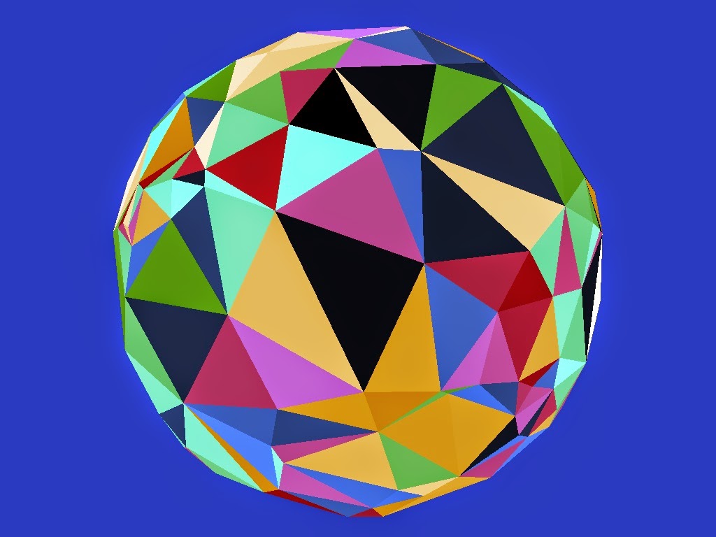
Triangulation of country control net created purely from seed points
For now I'm just using a sphere created by subdividing an Icosahedron for my planet's terrain and it's purely spherical with no elevation variation to ease visualisation.  Taking the centroid of each terrain triangle and shooting a ray from it normal to the surface against the country boundary control net described above then colouring the terrain triangle with the country ID proves the concept of determining countries from surface points:
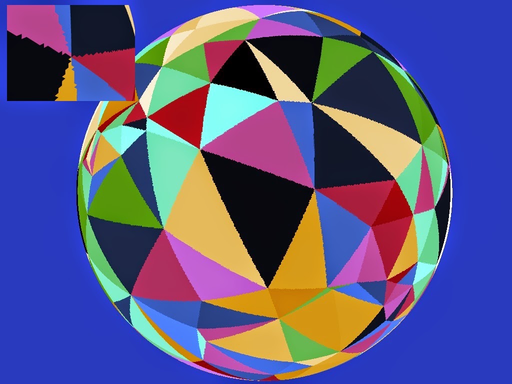
Countries found by ray-casting from the surface
Note the jagged edges of the triangles here (shown in close up in the top corner) in contrast to the smooth ones in the direct rendering of the control net above - remember this second image shows the individual terrain triangles flat shaded, effectively point sampling the country control net.

Unless you know of a planet with purely triangular countries though it's not particularly realistic.  To make the results a bit more organic I played with adding some noise to the vector shot from the surface against the control net which initially produced some slightly more encouraging results:
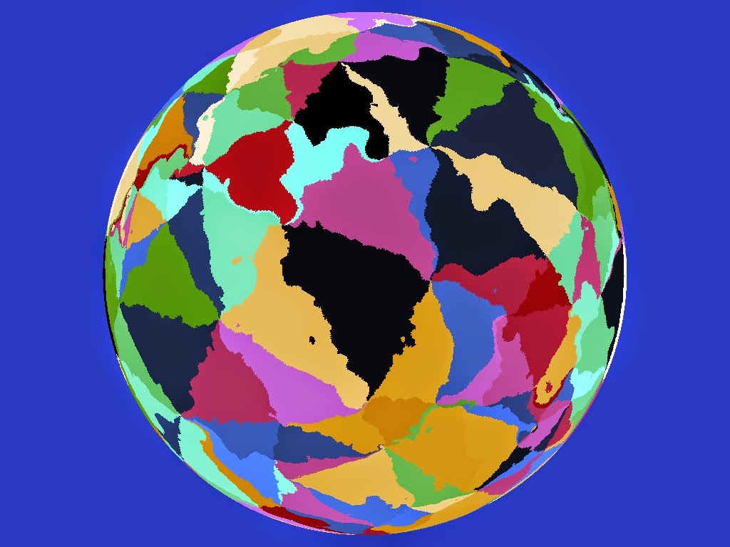
Perturbing the ray from the surface
The triangular nature of the control net however is still quite apparent and more problematically closer examination reveals there are problem cases where the noise causes unrealistic "bubbles" of a country to leak into adjacent countries due to the perturbation of the vectors being intersected against the control net.  This occurs most near the country boundaries as points on one side can end up being displaced enough to end up embedded in the neighbouring country:
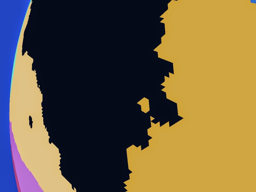
"Bubbles" of one country leaking into it's neighbour
This is not something you generally see in the real world and was what I felt to be an unacceptable results which unfortunately I couldn't think of a way to correct.  I ruled out noise perturbation as a result and went back to the drawing board.

Edge Subdivision 


Instead of noise then I had to come up with plan B - my second approach was to subdivide the edges of the triangles adding displacements to the introduced points to make the edges more interesting.  In this way the boundaries can be more interesting while still preventing "bubble" errors.  The process here is to recursively divide any boundary edge over some minimum length introducing a new boundary point in the middle of it.  The cross product of the edge vector and the normal gives a tangent which is used to displace this new point by some random amount.  The magnitude of this displacement is capped to be a proportion of the length of the edge so long edges have their midpoint displaced further than short edges to keep things in proportion.

Subdividing the edges did turn my nice triangles into n-gons so I also had to add in a triangulation step to turn each set of country boundary points back into a mesh I could both ray test against and render for debugging purposes.  As I knew the boundaries couldn't have holes I used the trusty Ear Clipping Algorithm as it's so simple to implement and fast enough for this case.

There is still a potential for error here though as there is a possibility that the displaced midpoint might end up within an adjacent country's boundary causing the boundary edges to intersect creating invalid boundary pockets:
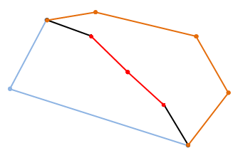
An edge between two countries that has been subdivided
Displacing the newly introduced midpoint perpendicularly to the edge by a distance proportional to the edge's length to make the boundary more interesting...

...but if you displace it too far the new edges can intersect the other existing edges of one or other boundary making an invalid boundary
So for each potentially displaced midpoint the two edges that would connect it to the original edge's end points are tested for intersecting any of the remaining edges of the two boundaries that adjoin across the edge being split.

If no intersection is found the displaced point is valid and I move on testing the two created edges to see if they in turn can be sub-divided, if however either of the two new edges intersect a remaining edge I have to pick a new position for the midpoint and try again.  To reduce the chance of getting stuck trying to find a valid position each time I have to reposition it I reduce the maximum magnitude of the displacement with each attempt so the new midpoint gradually tends back to the original edge.  If the magnitude gets so low it's not worth dividing the edge at all I just give up, leave the original edge undivided and move on to the next edge.  This only tends to happen in highly acute boundary corners where slivers are produced.

Running the process dividing any edge longer than 50Km gives a noticeably better result than the simple triangles I started with:
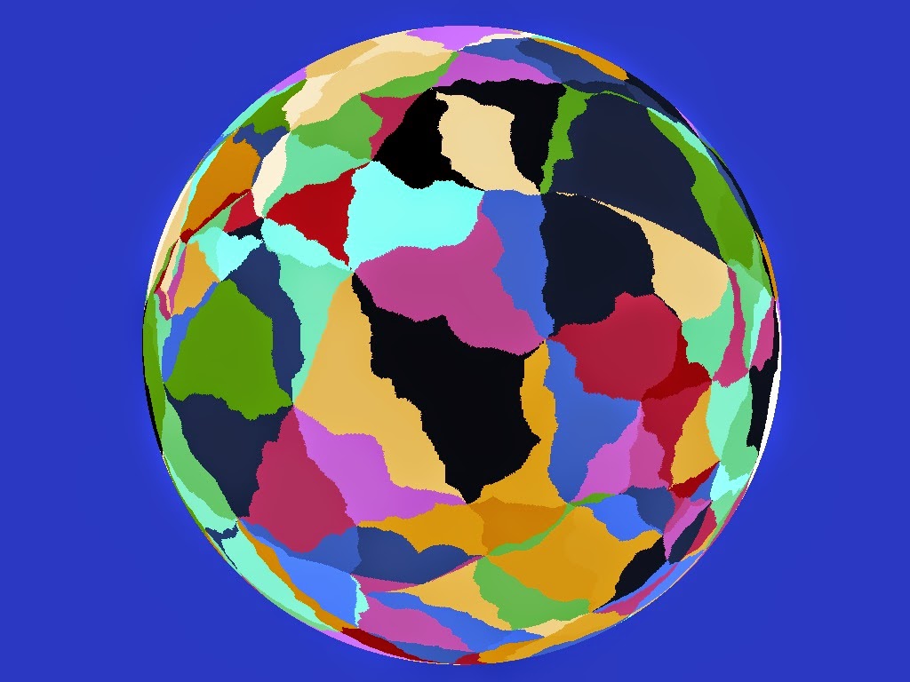
Country control net produced by subdividing edges of triangular countries
Although it's better there is no getting away from the fact that I started with triangles and I was still not particularly happy with it.  To make the country shapes more interesting my next step was to randomly take pairs of adjoining countries and merge them together producing fewer hopefully more interesting shapes:
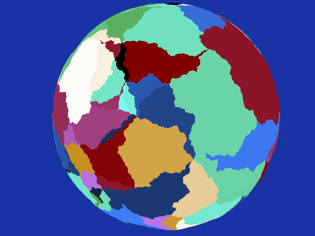
Randomly merging adjacent countries helps obscure their triangular origins somewhat
Another improvement but again to me it's still quite obvious I started with triangles - there are a large number of nexus points where to my mind an unrealistically high number of countries meet at a single place:
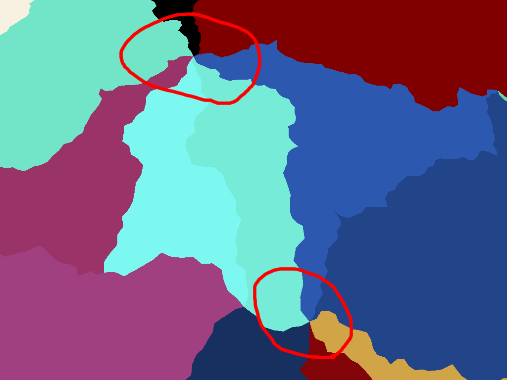
Unrealistic nexus points where many countries meet, another consequence of the triangular basis
I experimented with increasing the number of seed points which meant more smaller triangles to start with but although the effect was improved a bit more it felt more like treating the symptom than a cure.

Dual Meshing


Rather than shrink the triangles I thought it would be better to start from a more friendly base so instead of using the triangulation of the convex hull surrounding my initial seed points I instead calculated the dual of this mesh effectively producing faces surrounding each seed point rather than passing through them.  This immediately gave me what I thought was a better initial mesh, effectively similar to a 3D Voronoi diagram:
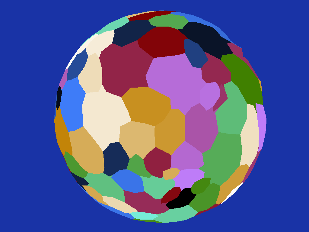
Using the dual of the triangular mesh produces better country shapes as a basis
Running the edge subdivision on this mesh finally gave me a result I was pretty happy with:
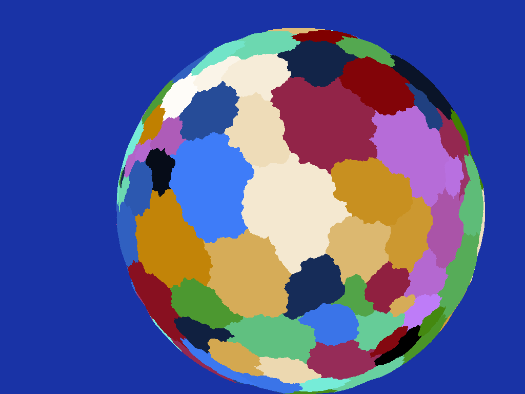
Subdividing the edges of the new countries makes them more realistic
I also added back the random merging of adjacent countries to make things more varied:
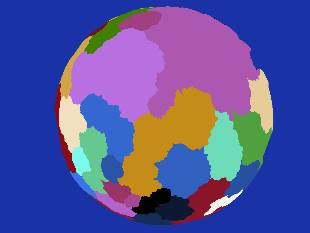
Randomly merging adjacent countries provides more variety of scale
Note how the irritating nexus points no longer feature, the countries join in what I feel to be a far more realistic manner.  The main issue I have with it now though is the countries before merging are a bit too similar in size causing the result to be a bit uniform - I think in the future I'll play around with clustering the seed points somehow instead of having them uniformly random and see how that affects things.

Note the triangulation of the country boundary control net doesn't necessarily produce a spherical mesh as such as the edges of triangles spanning large areas will at times be much closer to the centre of the sphere than their unit length vertices producing odd looking kinks in the geometry:
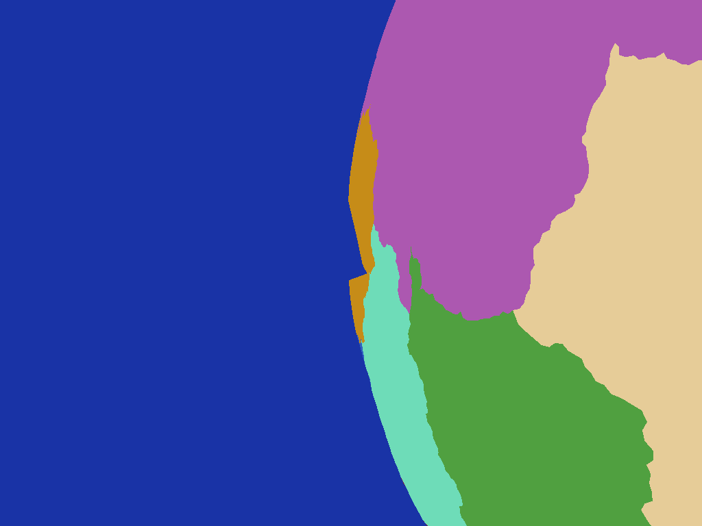
An obvious kink in the yellow country caused by the control net's triangles spanning a wide solid angle on the planet
this isn't a problem however as remember I'm not normally rendering the country boundary geometry directly, I'm just intersecting rays shot from the far denser planet surface mesh against it to determine which country a point is located within.

A Note on Ray-Triangle Intersections


While working on this there were a number of times when I had to intersect rays or 3D line segments with triangles.  I was using a trusty old intersection routine I've had kicking around for years but found that even with double precision there were times when a ray or line would be reported as missing a triangle that it really should have intersected, usually when falling on an edge between two adjoining triangles.  Puzzled by this I did a little research (i.e. consulted Google) and found a better intersection algorithm specifically designed for intersecting with meshes, "Watertight Ray/Triangle Intersection"

Implementing this solved all my problem cases in one fell swoop so it turned out to be a good find, if you are interested in using it do note however that there appears to be a minor error in the code presented in the paper, see near the bottom of this blog post for more info.

Conclusion


Although this has been focussed on country generation, while working on it I have thought that the system could also be used to produce areas of water for oceans and seas by simply flagging certain boundaries as water zones.  This would produce some nicely shaped features while avoiding the problem of parts of a country being underwater if water was placed by a different system.  I will need to feed the country boundaries into the elevation production system however for this to work so the water zones and coastlines are given appropriate topology.  Something for the future anyway.

So there you have it, a set of what I feel are quite realistically shaped countries I can use to move on to the next step, possibly placement of towns and cities followed by primary road or rail networks...that sounds like it should be interesting to look into anyway.